What is Moment Resisting Frame?
Important Point
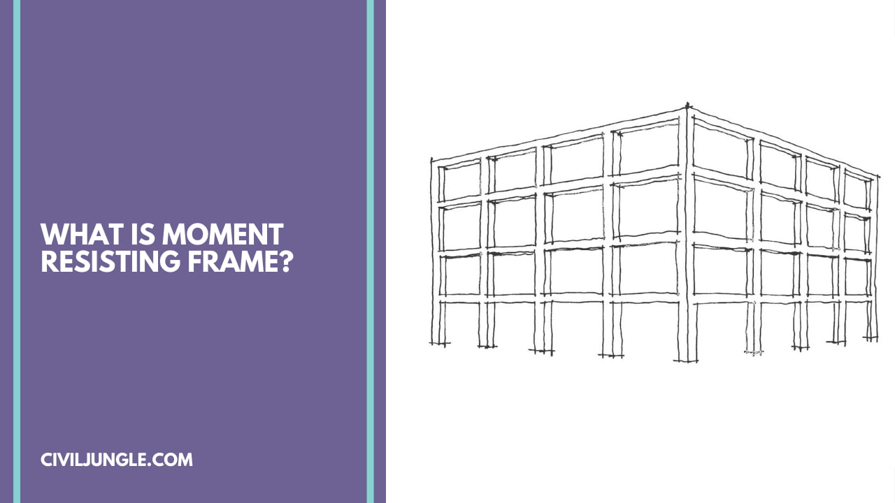
The Moment-resisting frame is a rectilinear gathering of beams and columns, in which the beams are inflexibly joined to the columns. Protection from parallel forces is given chiefly by unbending frame activity by the advancement of bending moment and shear force in the frame individuals and joints.
Under the unbending bar segment associations, a moment frame can’t dislodge horizontally without bending the beams or columns relying upon the math of the affiliation.
The bending rigidity and strength of the frame individuals are the essential wellsprings of sidelong firmness and force for the whole frame. In moment resisting frames, the joints or associations among columns and beams are intended to be unbending.
This makes the columns and beams twist during a seismic tremor, so these primary individuals are intended to be solid in bending. These frames are trusses without corner to corner supporting, so the shear forces following up on the construction should be opposed as moments in the joints among beams and columns.
The subsequent design is more generous than a truss with askew propping yet embraced where such supporting burdens its utilization, i.e., at divider openings. These moment-resisting frames are called special moment frames due to these extra necessities, which improve the inelastic reaction attributes of these frames.
Primary tests have shown that steel moment-resisting frames may give fantastic malleability and inelastic conduct under extreme seismic stacking. Since these frames are much of the time very adaptable, float restricts frequently control the plan.
Also, read: What Is Rolling Margin | The Procedure of Rolling Margin
Useful Article for You
- What Is a Contour Interval
- What Is Tile
- What Is the Difference Between a Shower Pan and a Shower Base?
- What Is a Window Panel
- Type of Arch
- What Is a Frame Structure
- What Is the Measurement for a Queen Size Bed
- What Is Considered Livable Space
- What Is One Way You Can Save Electricity?
- What Is Mdf Mean
- What Is a Bundle of Shingles
- What Is a Gallon of Water Weigh
- What Is SuperelevationWhat Is Overhang
- What Is Sand Blasting
- What Is a Span Bridge
- What Is the Little Black Diamond on a Tape Measure
- What Is a Louvered Door
- What Is a Spread Footing
- What Is Leveling
- Different Types of Beam
- What Is Pedestal
- What Is Plumbing Fixtures
- What Is Slab Construction
- What Is Calacatta Quartz
- What Is Auxiliary View
- Sheepsfoot Roller
- Live Load Vs Dead Load
- What Is 1 Flight of Stairs
- What Is Refractory Cement
- What Is Luminous Flux Vs Lumens
- What Is a Frost Wall
- What Is an Undercoat
- What Is Road Pavement
- Arch Foundation
- What Is a Stair Landing
- What Is Stone Masonry
- What Is a Spandrel Beam
- What Is Pier and Beam Foundation
- What Is Levelling
- What Is a Pile Cap
- What Is a Mat Foundation
- What Is a Floating Slab
- What Is the Purpose of Foundation
- What Is Modulus of Rupture
- What Is a Flush Door
- What Is Residential Construction
- What Is the Best Foundation for a House
- What Is Oblique Drawing
- What Is a Benchmark in Surveying
- What Is a Engineering Drawing
- What Is an Admixture
- What Is a Monolithic Slab Foundation
- What Is the Standard Size Water Supply Line
- What Is the Difference Between Tension and Compression?
- What Is a Tremie
- What Is Tributary Area
- What Is Shoring Construction
- What Is a Cason
- What Is Wall Putty
- What Is the Difference Between Mortar and Concrete
- What Is Bhk
- What Is Sbc of Soil
- What Is Plinth Level
- What Is Water Proofing
- What Is Mix Design of Concrete
- What Is Fine Aggregate
- What Is Retention Money
- What Is Design Mix
- What Is Isometric Scale
- What Is Development Length
- What Is Superelevation
- What Is Wall Made Of
- What Is Micro Piling
- What Is Soil Stack
- What Is a Half Wall Called
- What Is Flagstone
- What Is a Cinder Block
- What Is Plinth
- What Is Floors
- What Is Centering in Construction
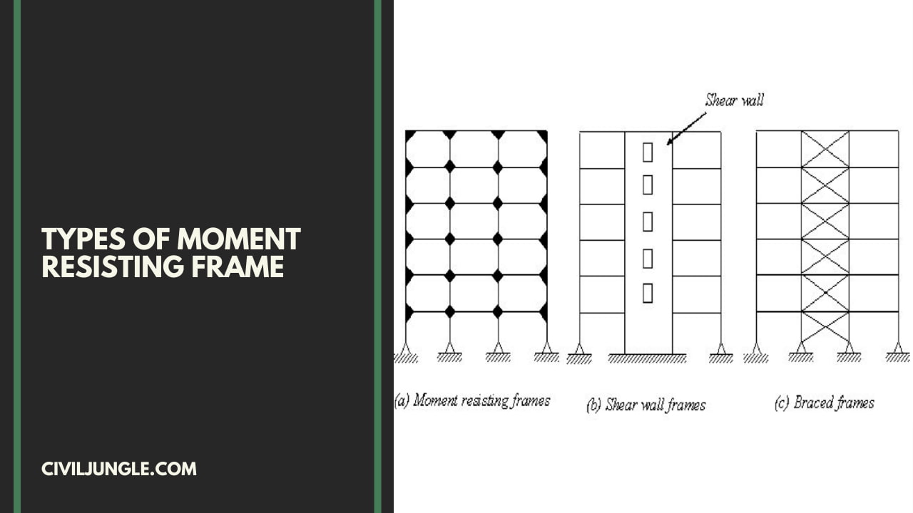
Types of Moment Resisting Frame
There are three types of Moment Resisting Frame:
- IMRF: Intermediate Moment Resisting Frame.
- SMRF: Special Moment Resisting Frame.
- OMRF: Ordinary Moment Resisting Frame.
1. Intermediate Moment Resisting Frame ( IMRF)
When subjected to the stresses resulting from the design earthquake’s motions, intermediate moment frames ( IMRF ) are expected to tolerate restricted inelastic deformations in their members and connections. The standards in this section must be met by the IMRF.
1.1. Beam-To-Column Connections
- The seismic load resisting system’s (SLRS) beam-to-column connections must meet the following requirements:
- An interstory drift angle of at least 0.02 radians must be maintained by the link.
- At an interstory drift angle of 0.04 radians, the measured flexural resistance of the connection, measured at the column face, must equal at least 0.80Mp of the linked beam.
- For the earthquake load impact E, the required shear strength of the connection shall be derived using the following quantity:
E = 2[1.1RyMp]/Lh.
1.2. Beam Flanges
- In plastic hinge zones, abrupt changes in beam flange area are not permitted.
- If testing or qualification shows that the resulting design may create stable plastic hinges, drilling of flange holes or trimming of beam flange width is allowed.
1.3. Lateral Bracing of Beams
- Both flanges must be supported laterally in some way, either directly or indirectly. Between the lateral braces, the unbraced length must not exceed 0.17ryE/Fy.
- Where research shows that a plastic hinge will form during inelastic deformations of the IMF, lateral braces should be positioned near concentrated loads, changes in cross-section, and other areas.
- The required strength of lateral bracing close to plastic hinges is
Pu = 0.06 Mu/ho (LRFD) .
or
Pa = 0.06Ma/ho (ASD).
-
- Where, ho is the distance between flange centroids.
Also, read: IS 516:1959 Most Important Point (Method of Tests For Strength of Concrete)
2. Special Moment Resisting Frame ( SMRF )
Whenever applied to the stresses arising from the design earthquake’s motions, special moment frames ( SMRF ) are supposed to survive considerable inelastic deformations. The conditions in this section must be met by SMRF.
2.1. Beam-To-Column Connections
The following three conditions must be met by beam-to-column connections used during seismic load resisting systems (SLRS):
- An interstory drift angle with at minimum 0.04 radians must be maintained by the link.
- At an interstory drift angle of 0.04 radians, the observed flexural resistance of the connection, evaluated at the column face, must approximate at minimum 0.80Mp of the linked beam.
- For the earthquake load impact E, the required shear strength of the connection shall be derived using the following quantity:
E = 2 [1.1 Ry Mp] / Lh.
-
- Where,
- Ry is the ratio of the expected yield stress to the minimum yield stress specified.
- Fy Mp = kip-in nominal plastic flexural strength (in N-mm)
- Lh is the distance between the sites of the plastic hinges in inches. (in mm)
2.2. Conformance Demonstration
The following conditions must be met by beam-to-column connections utilized in the SLRS:
- The use of SMF connections has been planned.
- Using a connection that has been pre-qualified for SMF.
- Results of qualifying cyclic tests are provided. At least two cyclic connection tests must be performed and the results must be supplied.
Also, read: 23 Different Types Cements Available in India and As Per IS Standards
2.3. Panel Zone of Beam-To-Column Connections
- The required panel zone thickness must be calculated using the same approach that was used to measure the panel zone of the verified or preapproved connection.
- The necessary shear strength of the panel zone shall be established at a least by adding the predicted moments at the plastic hinge points to the column faces and calculating the total of the moments at the column faces.
- The design shear strength shall be φv Rv .
- The allowable shear strength shall be Rv / Ωv.
- Where,
φv = 1.0 ( LRFD ) Ωv = 1.50 ( ASD ).
-
- The nominal shear strength, Rv, according to the limit state of shear yielding.
2.4. Panel Zone Thickness
- The thicknesses of column webs and doubler plates, if used, shall conform to the following requirement:
t ( dz + wz ) / 90
- Where,
- t = thickness of column web or doubler plate, in. (mm)
- dz = panel zone depth between continuity plates, in. (mm)
- wz = panel zone width between column flanges, in. (mm)
2.5. Panel Zone Doubler Plates
- Doubler plates must be welded to the column flanges employing a completejoint-penetration groove-welded or fillet-welded joint that creates the whole doubler plate thickness’s potential shear strength.
- When doubler plates are welded against the column web, the top and bottom edges must be welded together to develop the proportion of total force transmitted to the doubler plate.
- When doubler plates are installed away from the column web, they must be symmetrically arranged in pairs and welded to continuity plates in order to develop the proportion of total force transmitted to the doubler plate.
Also, read: IS 516:1959 Most Important Point (Method of Tests For Strength of Concrete)
Useful Article for You
- Zero Force Members
- How Much Does a Yard of Concrete Weigh
- Cmu Wall Meaning
- Gradient Road
- Budget Sunroom Ideas
- Types of Vaulted Ceilings
- Well Points
- How Does Baking Soda Remove Blood from Carpet
- What Are Forms in Construction
- How Heavy Is Dirt
- Tender Meaning in Architecture
- Dark Olive Green House
- Cast in Place Concrete
- Lean to Roof
- How Tall Is an Average Door
- Grade Beam Foundation
- Window Sill Height
- Concrete Cold Joint
- Types of Traps
- Types of Pipe
- Wood Supporting Beams
- Home Depot Scrap Wood
- Lvl Beam Size Calculator
- Structural Shell
- Curb Types
- Msand
- Optimum Dry Meaning
- Disadvantages of Low-E Glass
- Bridge Abutment Definition
- Composite Masonry Wall
- Is Cedar a Hardwood or Softwood
- Modified Proctor Test
- Physical Properties of Sand
- Sugar in Concrete
- Crane Machine Construction
- Types of Gable Roofs
- Door Frame Types
- How Much Does 55 Gallons of Oil Weigh
- Dog Leg Stairs
- Concrete Salt Finish
- Westpoint Bridge Builders
- Types of Porches
- Roof Pitch Types
- Types of Weirs
- Asphalt Floor
- Dutch Roof
- #6 Rebar Weight Per Foot
- Prizmatic Compass
- Bond Break Concrete
- Poured Concrete Wall Cost Calculator
- How Many 60 Lb Bags of Concrete in a Yard
- Wood Fence Post Spacing Chart
- Falsework
- Design of Building Structures
- Topping Slab
- Types of Cinder Blocks
- Fresh Concrete
- Door Colors for Red Brick House
- Foundation Spalling
- Clear Cover Concrete
- Tiles Brand
- Cement Consumption in Plaster
- Aggregate Density Kg M3
- Load Bearing Wall Construction
- Weight of Concrete Slab Calculator
- Is Clay Smaller Than Silt
- How to Calculate Dead Load
- Bad Concrete Work
- Stepped Foundations
- Residential Construction Cost Estimator Excel
- Different Construction Trucks
- Septic Pump Replacement Cost
- What Is Rcc Value Day
- What Is a Highway Flyover
- Tie Beam Concrete
- Cyclonic Precipitation
- M30 Concrete Ratio
- Top 20 Pvc Pipe Brands in India
- Footing Vs Foundation
- Parts of an Arch
3. Ordinary Moment Resisting Frame (OMRF)
Whenever applied to the stresses arising from the designed earthquake’s motions, ordinary moment frames (OMF) are intended to endure negligible inelastic deformations in its members including connections. The criteria of this Part must be met by OMF.
3.1. Beam-To-Column Connections
- Welds and/or high-strength bolts are required for beam-to-column connections. As seen below, connections can be fully restrained (FR) or partially restrained (PR) moment connections.
- The required flexural strength of FR moment connections that are part of the seismic load resisting system (SLRS) shall be equivalent to
1.1RyMp (LRFD) or (1.1/1.5)RyMp (ASD)
- As appropriate, of the beam or girder, or the maximum moment that the system can create, whichever is smaller.
Also, read: What Is Rolling Margin | The Procedure of Rolling Margin
3.2. FR Connections Shall Meet the Following Requirements.
- Steel backing and tabs must be removed from connections with complete-joint-penetration (CJP) beam flange groove welds, with the exception of top-flange backing joined to the column by a continuous fillet weld on the edge below the CJP groove weld.
- Where weld access holes are required, they must be positioned. The surface roughness of the weld access hole must not exceed 500 in. (13 m), and it must be free of notches and gouges.
- Notches and gouges must be corrected according to the engineer of record’s specifications. In bolted moment end-plate connections, weld access holes in the beam web adjacent to the end-plate are prohibited.
- The necessary strength of double-sided partial-joint-penetration groove welds and double-sided fillet welds in connections that withstand tensile forces is 1.1RyFyAg (LRFD) or (1.1/1.5)RyFyAg (ASD) of the connected element or part, as appropriate. To resist tensile stress in the connections, single-sided partial-joint-penetration groove welds and single-sided fillet welds must not be employed.
- For FR moment connections, the needed shear strength, Vu or Va, is obtained by multiplying the earthquake load impact E by
E = 2[1.1RyMp]/Lh.
3.3. Requirements for PR Moment Connections
- When the following conditions are met, PR moment connections are permitted:
- such connections must be designed for the requisite strength.
- The connection’s notional flexural strength, Mn, must be at least 50% of the connected beam or column’s Mp, whichever is lower.
- The stiffness and strength of the PR moment connections, as well as the effect on overall frame stability, must be considered in the design.
- For PR moment connections, Vu or Va should be calculated using the load combination above plus the shear caused by the maximum end moment that the connection can withstand.
Moment Frames
A moment frame is a special type of frame that uses rigid connections between each of its constituent members.
Structural Moment Frame
This configuration is able to resist lateral and overturning forces because of the bending moment and shear strength that is inherent in its members and the connecting joints.
Steel Moment Frame
A steel moment-frame is an assembly of beams and columns, rigidly joined together to resist both vertical and lateral forces. Construction of a modern steel frame building in which the ends of beams are rigidly joined to columns by welded connections.
Special Moment Frame
Structural steel special moment frames (smf) are typically comprised of wide-flange beams, columns, and beam-column connections. Connections are proportioned and detailed to resist internal forces (flexural, axial, and shear) that result from imposed displacement as a result of wind or earthquake ground shaking.
Like this post? Share it with your friends!
Suggested Read –
- Vitrified Tiles Meaning
- What Is Grouting | Type of Grouting | Advantage of Grouting
- What Is Workability of Concrete | Factors Affecting Workability | Test |Errors
- What Are Construction Contract | Types of Engineering Contracts | Percentage-Rate Contract
- What Is the Penetration Test | What Is the SPT Test | Procedure | Efficiency | Advantages and Disadvantages
- Polysulfide Sealant Vs Polyurethane Sealant | Functions of Sealants | What Is Polysulphide Sealant | What Is Polyurethane Sealant
- What Are Survey Levelling | Important Terms Related to Levelling | What Are Different Types of Levelling | Types of Trigonometric levelling
- Parking In India | What Is Parking | Parking Statistics | Types of Car Parking | How to Park a Car Perpendicular | Types of Parking Spaces




Leave a Reply